Wednesday, April 23, 2025

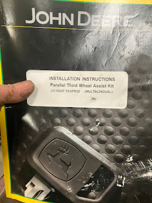
JD 2500E third wheel parallel wheel assist kit

Getting a new 2500E. 
We are going to use one of the old units for tee and approach mowing freeing up 3 staff for other jobs.
Instructions are ok and just follow them in order.


Started of removing the cab for easier access to change rear steering arm.

Lot of parts.
I did preassemble what I could on the roll top.  

 
This plate the instructions don't show where it goes exactly.
Goes on motor mount.
Remove reels for better access and support engine.
Remove bolts and use bolt provided to install plate.
  

I'm supporting machine on tripods using my lift.
Remove wheel to lighten the load and to have enough room to slide out.   


This small Allen headed bolt is slide into the grove to hold steering arm in. 


Remove this ram connection and get the other side when steering arm is lowered.


Grease shaft and partially put in place and reconnect steering ram.


Now attach the other end after securing shaft in place with set screw bolt. Use red Loctite on these Allen bolts. 


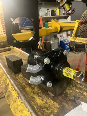
Line up motor and tighten down evenly till its touching.
It was a tight fit. Back nuts off and torque to spec.


Install wheel hub and torque to 150 ft lbs


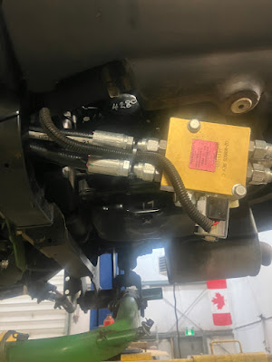
Start routing hose as per manual.
they should cross over like this.


Two remaining hoses, the longest one will go to right side and attach to left side fitting on steel wheel motor lines. 


Caps for connection points.


Took me a few tries to route the hoses to get the least chaffing.


After attaching connection points you can use zip ties in kit to tidy things up.


Mine looks like this. 
Looking from behind front lift arm.
Left connection point is the longer hose.


On to wiring.


Remove two bolts to move axillary tank aside to get to grounding access point on back side of bolt shown in manual 15mm wrench nut.


Connect this wire.


The other end attaches on the E type machines on the white connector behind right front wheel.
Remove the rubber plug and install the pin through same connecter.


Zip tie everything up and out of the way so middle deck doesn't hit it. 


Bleeding some air out of lines.


Ready for next mow. The coil is only activated when lever is in mow.

Tuesday, November 19, 2024

Adjusting front and top face from pivot bolts (Bernhard)

Recently view a you tube video from Trent Manning about measuring from bedbar pivot bolts.

Always wanted to do the same but couldn't figure out an easy way to do it.

This is my version I came up with for my grinder type.


Amazon linear digital gauge.
Not to expensive 50$ Can + -


I'll be using to old mounts for what looks like stone sharpener.
Installed 10 mm bolts.

 
Drilled out holes in lol near center of bedbar pivot bolts.


Mount to bedbar and then use the holders from grinder.
Gives an accurate area to measure from.


Had a piece of aluminum plate and cut a couple of slices in it to mount gauge.


Test fitting it to a piece of 3/8 rod I had around the shop.


Installed rod then attach plate to it.
It can also adjust in and out If I needed to. 


Like this.
Turned out pretty good.


Brand new bedknive I had ground as per grinding instruction to find that this on was of by less than a hair.


Checking to see if by moving it back and forth on rail If the readings stay consistent and they do. 


This bracket that came with gauge I just flattened out to attach to the end so I can adjust top or front face by just tipping bracket to the side a bit.


Top face 
The add bracket stays on to catch the bedbar pivot bolt in either top or front face grinding 


Front ... notice the bracket is tipped to right to catch the pivot bolt.


A couple of videos

So now when my leading edge is worn back on top dress days and touching both ends for set up leaves it a bit off I'll be able to set them all up the same and back to the correct front face. 

Should be a game changer in this situation for sure